|
Details About the Parts
Introduction The radial engine plans are the product of more than 70 years of development and refinement. The improvements have come from personally building the engines as well as comments, suggestions and improvements made by other builders.This process of improvement continues to this day. The photos and descriptions below are to acquaint the potential builder and enthusiast with the design effort that has gone into these plans. This is not a hard engine to build, it is a bit time consuming. Better then watching television ! Many builders have told me this is the first engine they have found that is " A Joy to Build ".As I build the engines I am constantly amazed with the subtle thought that went into the original work. ~~~~~~~~~~~~~~~~~~~~~~~~~~~~~~~~~~ Important Features The various views and pictures shown below are from different engines to illustrate important features common to all the engines.
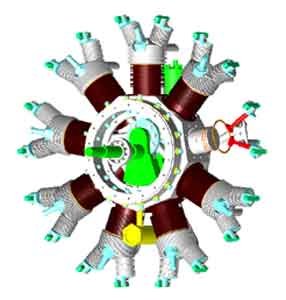  Front View
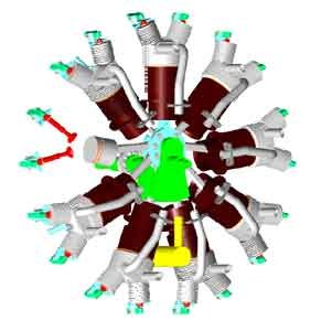
Rear View
Front View
Rear View
~~~~~~~~~~~~~~~~~~~~~~~~~~~~~~~~~~ The Crankcase 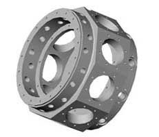 The front cover
carries the thrust load into the crankcase using a ball
bearing. None of the thrust load is carried by the crankshaft main
bearings.
The front cover
carries the thrust load into the crankcase using a ball
bearing. None of the thrust load is carried by the crankshaft main
bearings.
The crankcase is machined from a 5.25 diameter 6061-T6 aluminum round. If you don't have a source for material, see ASAP's web site. ( See the supplier list ). The front and rear cover is piloted to the main crankcase to ensure concentricity with the two main bearings.The bearing diameter and the pilot diameter are machined during the same setup to ensure concentricity. The support rings inside the crankcase are used to pilot the crankshaft main bearings to ensure a rugged assembly.The cylinder skirt studs are secured in blind holes to reduce oil leakage. ~~~~~~~~~~~~~~~~~~~~~~~~~~~~~~~~~~The Rear Cover 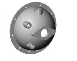 This is the only
casting used in the engine. It is 356-T6 material, heat treated to
ensure it will machine beautifully.
This is the only
casting used in the engine. It is 356-T6 material, heat treated to
ensure it will machine beautifully.
A chucking boss provides easy cleanup of the mounting flange. After the boss is removed, the flange is used to mount the carburetor. On the single row engines, the casting supports the carburetor, the distributor assembly and the two oil lines.For the double row engines, the casting supports two distributors and the carburetor. The shape of the casting and air guide keeps the speed of the fuel/air mixture high and reduces fuel pooling in the lower cylinders.~~~~~~~~~~~~~~~~~~~~~~~~~~~~~~~~~~ Main Bearing 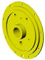 The main
bearings are 660 bearing bronze. On the front main
bearing, the cam runs on a machined lip.
The main
bearings are 660 bearing bronze. On the front main
bearing, the cam runs on a machined lip.
The rear main bearing supports the oil pump housing and the oil pump shafts as well as the crankshaft. Oil from the pressure pump is supplied to the crankshaft at the rear main bearing. ~~~~~~~~~~~~~~~~~~~~~~~~~~~~~~~~~~ Jack Shaft & Cam Support 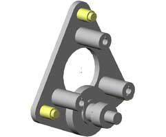 The jack shaft is
used to drive the cam at the 8:1 reduction. The gears are purchased from
Boston Gear. ( See supplier list ). The jack shaft is piloted into
the front main bearing, the other end is mounted in a bronze bushing
located on the aluminum cam support base.
The jack shaft is
used to drive the cam at the 8:1 reduction. The gears are purchased from
Boston Gear. ( See supplier list ). The jack shaft is piloted into
the front main bearing, the other end is mounted in a bronze bushing
located on the aluminum cam support base.
The cam support plate has three nylon pads that hold the cam ring into the front main bearing support ring. ~~~~~~~~~~~~~~~~~~~~~~~~~~~~~~~~~~ Cam Ring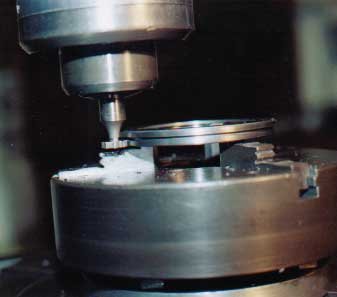 The cam is a single
steel ring. The intake and exhaust lobes are machined in a single setup.
The cam is a single
steel ring. The intake and exhaust lobes are machined in a single setup.
~~~~~~~~~~~~~~~~~~~~~~~~~~~~~~~~~~ Cylinder Heads 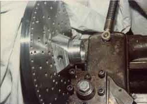 The cylinder heads
are the most important part of the engine. They are machined from
6061-T6 aluminum bar stock. The cylinder barrels and the heads are
screwed together. A few of the important steps are shown.
The cylinder heads
are the most important part of the engine. They are machined from
6061-T6 aluminum bar stock. The cylinder barrels and the heads are
screwed together. A few of the important steps are shown.
The beginning step in making the cylinder heads is shown. The raw material block is drawn up to the face plate with a bolt. The bolt thread is located between what will eventually become the valve towers. At this step. the base of the cylinder head is turned and finned. In the same setup, the inside of the dome is formed and the thread is generated.The material is roughed out around the towers. The wedge tool provides the correct angle and the necessary stiffness to turn the towers to the finished diameter and cut the fins using a hook shaped finning tool.  The drawings for the
wedge tool and dimensions for the finning tools are included in the
engine plans.
The drawings for the
wedge tool and dimensions for the finning tools are included in the
engine plans.
~~~~~~~~~~~~~~~~~~~~~~~~~~~~~~~~~~ Cylinder The cylinders are machined from free machining leaded steel. After roughing out the bore, the blanks are mounted on a mandrel. This saves the lathe setup and makes the repetitive finning go faster and more accurately. The support from the tail stock greatly improves the rigidity of the setup.Following the finning operation, the thread is machined during a second setup on the mandrel. After machining, a hot gun blue finish is used to prevent rusting. A drawing of the mandrel tool is included in the engine plans.
~~~~~~~~~~~~~~~~~~~~~~~~~~~~~~~~~~ Crankshaft  To ensure crankshaft
straightness, the crank throws are machined as a bolted pair. A 3/8
square broach is used to make the square hole. The part number and
source for the broach are included in the plans.
To ensure crankshaft
straightness, the crank throws are machined as a bolted pair. A 3/8
square broach is used to make the square hole. The part number and
source for the broach are included in the plans.
The square hole takes the torque of the engine, while the 3/0 taper pins hold the various shaft parts together. ~~~~~~~~~~~~~~~~~~~~~~~~~~~~~~~~~~ Gear Cutting The gears can be
purchased. With the higher power of the double row engines, the
crankshaft gears can be cut integral to the shaft.
The gears can be
purchased. With the higher power of the double row engines, the
crankshaft gears can be cut integral to the shaft.
Part numbers and sources for the cutters are called out in the engine plans. The air and oil passages are drilled using a Guhring parabolic drill. This special shape promotes chip removal and allows the small deep holes to be drilled with confidence.The crankcase is equipped with a breather hole in the front of the crankshaft. This small hole creates just enough back pressure in the crankcase to force the oil into the sump.
This is one of my favorite photos. The crankshaft with the master rod, slave rods and pistons. ~~~~~~~~~~~~~~~~~~~~~~~~~~~~~~~~~~ Master Rod  The master rod tool
is typical of the tools shown in the plans. Using this tool, it is
possible to turn the overall shape, mill the flats between the support
rails and mill the 3/4 degree taper to the rod.
The master rod tool
is typical of the tools shown in the plans. Using this tool, it is
possible to turn the overall shape, mill the flats between the support
rails and mill the 3/4 degree taper to the rod.
Nothing you couldn't design for yourself, but it's all documented in the engine plans for you to use. The tool design saves you a lot of time. ~~~~~~~~~~~~~~~~~~~~~~~~~~~~~~~~~~ Pistons The pistons are made from 2024 aluminum round for the better strength. There are two compression rings above the wrist pin. The oil control ring is below the wrist pin. The oil ring groove has 8 radial holes that provide a return path for the oil back to the crankcase.~~~~~~~~~~~~~~~~~~~~~~~~~~~~~~~~~~ Piston Rings The piston rings are made of fine grain cast iron.There are two compression rings above the wrist pin, and an oil control ring below the wrist pin. The oil control ring is grooved between the two lands. A series of radial holes between the lands leads the oil to a set of radial holes in the piston skirt, and then back to the crankcase. The rings are turned and parted off from the stock. Then, are cleaved using a tool that is included in the plans. Fracturing the rings means there is no lost material in the gap. An additional tool is used to anneal the rings before assembly to the pistons. A chamfer on the bottom of the cylinders is used to compress the rings during assembly. The plans also include the use of mineral oil to help break-in the piston rings. ~~~~~~~~~~~~~~~~~~~~~~~~~~~~~~~~~~ Oil System The radial engines are equipped with a pressure pump and a scavenge pump. Both of these are gear pumps mounted in the same housing and driven from a common crankshaft gear.The pressure pump draws oil from the supply tank and forces oil onto a ring slot in the engine main bearing. This slot ensures the oil will enter the crankshaft passages regardless of crank position. The drilled oil passages carry oil to the master rod throw and then to the other main bearing. The oil is allowed to escape from the main bearing to lubricate the cam and cam drive gear.The oil then flows into the sump. From the sump, the oil is scavenged by a pump larger than the pressure pump. The oil is returned to the supply tank by the scavenge pump.~~~~~~~~~~~~~~~~~~~~~~~~~~~~~~~~~~ Electronic Ignition System The distributor rotor has a series of magnets, one for each cylinder. A hall effect sensor is pulsed by the passing magnet and sends a signal to the ignition electronics. The electronics controls the flow of current from the battery to the ignition coil.The distributor cover is made from black Delrin, a plastic material with superior characteristics to modern plastics under these high voltage conditions.
|