|
Why does a Radial Engine always
have an odd number of cylinders
?
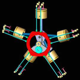
Any four stroke engine, regardless of construction, must fire all of the cylinders in two revolutions of the crankshaft. Unlike an automobile engine, a radial engine has only one crankshaft throw for all the cylinders in a bank. Remember that an 18 cylinder engine is just two 9 cylinder banks, set 180 degrees to each other. The firing order starts with the #1 cylinder at the top and proceeds around the engine in a counter clockwise direction as viewed from the front. The firing order progresses from the #1 cylinder, skips #2 cylinder and fires #3 cylinder. So in the first revolution of the crank, the firing order would be #1, #3, #5, #7 and #9. Using this skip and fire technique, the next cylinder to skip on the second revolution of the crankshaft, would be the #1 cylinder. On the second revolution of the crank, the firing order would be #2, #4, #6, #8. Again using the skip and fire technique, the #9 cylinder is skipped and the #1 cylinder is again ready to start the whole process over again. If there were an even number of cylinders, half would never be fired.
How does the cam work ? Consider a nine cylinder radial as an example. In a 9 cylinder, there are 40 degrees between the cylinders.Referring to the firing order explanation, the crank progresses two cylinders between firings, or 80 degrees. The cam drive gears are designed to run the cam 1/8 speed in the opposite direction as the crankshaft. This is accomplished with two stage gear reduction. A single jack shaft using a spur gear set makes a 2 to 1 reduction. On the other end of the jack shaft, a second stage reduction of 4 to 1 is made using an internal tooth ring gear mounted along the inside diameter of the cam ring. Other gearing combinations are possible, but are difficult to package in the limited space available in the crankcase. While the crankshaft is turning counter-clockwise, as seen from the front, through 80 degrees. At the same time the cam ring is turning 10 degrees in the opposite direction. The combination is 80 + 10 degrees. So there are four lobes, each at 90 degrees on both the intake and exhaust cam rows.
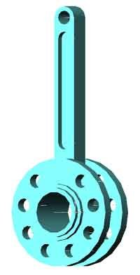
As shown in the picture, one cylinder is equipped with a " master rod ". On the crank throw end the master rod has two rails with holes to receive a pin from other rods. The remaining pistons have a connecting rod that is pinned to the two rails of the master rod. What is the firing order for a double row engine ? The firing order on a double row engine can be thought of as two single row engines firing 180 degrees apart. For this reason the crankshaft for a double row engine has two crank throws 180 degrees apart.Considering the rear row. The #1 cylinder fires, the #2 cylinder is skipped, then the 3rd cylinder is fired. When the #2 cylinder was skipped a cylinder 180 deg opposite and on the front row was fired. So, the complete firing order, counter clockwise from the front is : 1R - 12F - 5R - 16F - 9R - 2F - 13R - 6F - 17R - then - 10F - 3R - 14F - 7R - 18F - 11R - 4F - 15R - 8F
How is oil kept out of the lower cylinders ? A lip seal and " O " ring are located on a separator plate between the oil pump and the intake space prevents oil from entering the intake chamber. In addition, the cylinder skirts extend into the crankcase inside diameter. This keeps the oil from easily entering the cylinder bore. The oil is directed from the crankcase into the oil sump between the two lower cylinders. With these provisions, the two lower cylinders still require constant attention. When allowed to stand, without running, the oil can accumulate in the combustion chambers. When the piston reaches top dead center ( TDC ) there is no place for the oil to go.This is known as hydraulic lock. If steps are not taken to drain the oil, severe engine damage can result. To prevent hydraulic lock, the spark plug should be removed and the oil allowed to drain. Always be vigilant. Prior to starting, always turn the engine over slowly by hand, never force the engine to turn.
What is the difference between a Rotary and a Radial ? A rotary engine is characterized by a fixed crankshaft and cylinders that rotate. The propeller is attached to the spinning crankcase. A fuel metering carburetor is attached to the hollow fixed crankshaft. Air, fuel and castor oil ( for lubrication ), are drawn into the crankcase then pass through the intake pipes to the cylinders. The exhaust is timed to exit at the bottom of the engine to minimize interference with the pilot. This arrangement was common in World War I, when modern high-strength, heat resistant, steels were not commonly available. Cooling was accomplished by having the cylinders spin. This is completely different from the Wankel Rotary car engine developed in the 1970s.
What aircraft were these engines used on ? The single row engines were used on many light aircraft and single seat fighters. The 14 cylinder was used on aircraft like the PBY Catalina flying boat. The 18 cylinder was common on the Vought Corsair and the Grumman Hellcat. The BR-2 rotary was used by the British RAF in the " Snipe " aircraft as late as 1926.
How are the number of cam lobes determined ? The number of lobes, the gear ratio and direction of rotation are designed as follows : Where " X " is the number of intake or exhaust lobes on the cam. " Y " is the number cylinders, and " R " is the gear ratio relative to the crankshaft. For cams running in the opposite direction to the crankshaft X = ( Y - 1 ) / 2 and R = 1 / ( Y-1 ) For cams running in the same direction to the crankshaft X = ( Y + 1 ) / 2 and R = 1 / ( Y+1 ) Generally opposite rotation is favored as the cam speed is lower, this reduces the relative velocity between the cam lobes and the tappets, also it results in fewer lobes to be machined. There are two rows of cam lobes, one for the inlet valves and one for the exhaust valves. This allows the different inlet cam and exhaust cam durations to be optimized.
| ||||||